Why the PATC F Series Thermal PTZ Camera Is Ideal for Challenging Sea Conditions
You demand reliable technology to secure your vessel and navigate unpredictable waters. The PATC F Series thermal ptz camera stands out as your premier solution. You benefit from its dual payload system, which delivers clear visuals in any lighting. Its rugged design resists corrosion and extreme weather. Advanced tracking and stabilization features ensure that you maintain control and situational awareness, even during the roughest sea conditions.
Key Takeaways
-
The PATC F Series thermal PTZ camera offers high-resolution thermal imaging, ensuring clear visuals in darkness, fog, or heavy rain.
-
Its dual payload system allows seamless switching between thermal and optical views, enhancing navigation and security in all conditions.
-
Advanced radar integration and target tracking provide real-time data, improving situational awareness and threat detection at sea.
-
The rugged design, featuring anti-corrosive aluminum housing and IP67 weatherproof protection, ensures durability in harsh marine environments.
-
Digital stabilization technology keeps images steady, allowing for accurate monitoring even in rough sea conditions.
Thermal PTZ Camera Imaging Performance

High-Resolution Thermal Sensors
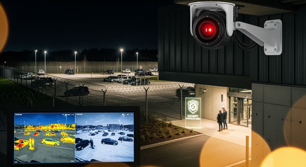
You rely on clear visuals to make critical decisions at sea. The PATC F Series thermal ptz camera uses advanced thermal imaging technology to deliver unmatched clarity, even in the most challenging conditions. You benefit from high-resolution sensors that capture detailed images in darkness, fog, or heavy rain. The camera’s uncooled thermal core ensures you receive continuous thermal images at a fast frame rate, so you never miss important details.
Here is a summary of the technical specifications that set this system apart:
|
Feature |
Specification |
|---|---|
|
Sensor Type |
Uncooled thermal core |
|
Resolution |
640x480 / 384x288 |
|
Frame Rate |
25Hz / 30Hz |
|
Additional Features |
Clear and continuous thermal images |
|
Zoom Module |
Integrated HAD 28X zoom module |
|
PTZ Precision |
±0.05 |
|
Weatherproof Rating |
IP67 |
|
Operating Temperature Range |
-45°C to 55°C |
You gain a significant advantage from the camera’s high thermal sensitivity. This feature allows you to detect subtle temperature differences, which is essential for identifying vessels, obstacles, or people in the water. The detection range of the thermal imaging cameras ensures you can monitor wide areas and respond quickly to any situation. You can trust this security camera to deliver reliable performance, no matter the weather or time of day.
Dual Payload for Day and Night
You face unpredictable lighting and visibility at sea. The dual payload system in the PATC F Series combines thermal and daylight imaging, giving you the flexibility to adapt to any situation. You can switch seamlessly between thermal and optical views, which enhances your ability to navigate and maintain security around the clock.
Tip: Use the dual payload feature to maximize your detection range during night operations or in foggy conditions.
You experience several key benefits with this dual payload system:
-
You achieve all-weather visibility by combining daylight and thermal imaging technology.
-
You support advanced tracking and detection, which improves your situational awareness.
-
You enhance safety during night operations or emergencies, when visibility is limited.
-
You gain a versatile solution suitable for commercial, law enforcement, and large vessels.
The dual payload system proves its value in demanding maritime tasks. You can navigate safely in low visibility, monitor for security threats, and support search and rescue operations. The thermal ptz camera enables you to detect obstacles, vessels, or individuals in the water, even when darkness or fog would defeat standard cameras. You maintain control and confidence, knowing your ptz system delivers continuous, high-quality imaging in every condition.

PTZ Tracking and Control
Radar Integration and Target Tracking
You need more than just clear visuals at sea. You require a system that actively tracks and identifies potential threats. The PATC F Series ptz camera delivers this advantage through advanced radar integration and target tracking. You connect the camera to your vessel’s radar using the NMEA0183 protocol. This integration allows the ptz system to receive real-time data and automatically track moving targets based on your current position.
You gain a comprehensive operational picture by combining radar with thermal imaging cameras. This fusion of sensor data, satellite imagery, and open-source intelligence gives you a structured understanding of your maritime environment. AI-driven analytics expose hidden activities, so you can make informed decisions quickly. With radar tracking, you achieve:
-
Situational awareness: You understand current conditions at sea.
-
Threat awareness: You identify potential risks before they escalate.
-
Response awareness: You determine the best actions for each situation.
You benefit from rapid collection and dissemination of information about emerging threats. The layered approach to monitoring and protecting your vessel supports effective and dynamic responses. You rely on the ptz system’s powerful target recognition and thermal sensitivity to detect vessels, obstacles, or people, even in low visibility. This capability extends your detection range and enhances your security camera’s effectiveness.
Pan-Tilt-Zoom Precision
You demand precise control when monitoring wide maritime areas. The PATC F Series ptz camera provides fast and accurate pan-tilt-zoom movement. You can sweep large sectors or focus on specific targets with ease. The system supports both coarse and fine control, allowing you to adjust quickly or make subtle corrections as needed.
|
Movement Type |
Range |
Control Type |
|---|---|---|
|
Pan |
540° |
Coarse & Fine Control |
|
Tilt |
260° |
Coarse & Fine Control |
You experience seamless operation, whether you use the optional maritime keyboard controller or the intuitive on-screen display menus. These user-friendly controls simplify navigation and management of complex ptz systems. You improve operational efficiency, as the interface allows you to log data and receive real-time feedback. This optimization helps you reduce fuel consumption and streamline your workflow.
You rely on the ptz camera’s thermal imaging technology and advanced pan-tilt-zoom features to maintain continuous surveillance. The system’s detection range and thermal imaging cameras ensure you never lose sight of important details. You stay in control, even in rough seas or during night operations.
Tip: Use the pan-tilt-zoom controls to scan large areas quickly, then zoom in for detailed inspection when you spot a potential threat.
You trust the PATC F Series ptz system to deliver reliable performance and unmatched clarity. The combination of radar integration, powerful target recognition, and user-friendly controls makes this thermal ptz camera an essential tool for maritime professionals.
Rugged Marine Design
Anti-Corrosive Aluminum Housing
You operate in an environment where saltwater, humidity, and harsh chemicals constantly threaten your equipment. The PATC F Series uses an anti-corrosive aluminum housing that stands up to these challenges. Unlike standard metals, this housing resists pitting and surface breakdown, which often compromise traditional marine camera housings. You benefit from a design that prevents seal fatigue and galvanic corrosion, extending the lifespan of your investment.
-
Engineered plastics, FRP/GRP composites, and coated metals provide superior resistance to harsh marine conditions compared to standard metals.
-
Stainless steel can corrode in chloride-rich environments, especially at seams and fasteners, but the PATC F Series avoids these weaknesses.
-
Corrosion-resistant housings can last for years or even decades, outlasting many aluminum or stainless steel options.
You can trust your thermal imaging cameras to deliver reliable performance, even after years of exposure to the sea. This robust construction ensures your system remains operational when you need it most.
IP67 Weatherproof Protection
You face unpredictable weather at sea. The PATC F Series offers IP67 weatherproof protection, which means your camera withstands heavy rain, salt spray, and even temporary submersion. You do not have to worry about water ingress or dust affecting your thermal imaging cameras. This level of protection ensures your equipment operates in extreme weather, from freezing cold to intense heat.
Your thermal ptz camera maintains its detection range and image quality, regardless of the conditions. The rugged design supports thermal imaging technology that keeps you aware of your surroundings. You can rely on your thermal imaging cameras to provide a consistent detection range, whether you encounter storms, fog, or rough seas.
Note: The combination of anti-corrosive housing and IP67 protection gives you peace of mind during every voyage.
Image Stabilization and Clarity

Digital Stabilization Technology
You operate in unpredictable sea conditions where vessel movement can disrupt your view. The PATC F Series ptz camera uses advanced digital stabilization technology to keep your images steady. This system works through a series of steps that ensure you receive clear visuals, even when your vessel rocks or pitches.
-
The digital stabilization process starts with motion estimation. The ptz camera analyzes changes between frames using models such as translation, affine, and similarity.
-
Next, motion smoothing comes into play. Filters like the Kalman filter or Gaussian low-pass filter reduce unintended motion, so your ptz system delivers a smooth video feed.
-
Finally, image warping adjusts the image plane, producing a stabilized output that you can rely on for accurate monitoring.
-
IMU sensors, which combine accelerometers and gyroscopes, enhance the ptz camera’s ability to track and compensate for movement.
You benefit from reliable stabilization that ensures crisp, clear imaging in any sea conditions. This feature is essential for high-performance vessels, emergency responders, and commercial shipping. You gain safer and more effective navigation, as your ptz system maintains a consistent detection range regardless of the weather.
Image Freeze and Enhancement
You often face fog, rain, or night conditions that challenge your ability to see details. The PATC F Series ptz camera offers image freeze and enhancement features that help you analyze critical moments. When you activate image freeze, you can pause both thermal and optical views, allowing you to inspect specific details without losing situational awareness.
Low-light image enhancement technology improves image quality in poorly lit environments. This technology reduces noise, restores detail, and increases contrast, making it easier for you to recognize objects and people. The ptz system’s enhancement algorithms outperform traditional methods, especially in foggy or hazy conditions.
|
Method |
Performance in Fog/Rain/Night |
Observations |
|---|---|---|
|
DDCGAN |
Poor |
Produces fuzzy and dark outputs. |
|
IFCNN |
Limited |
Black spot artifacts compromise image quality. |
|
STDFusion |
Limited |
Shows limited effectiveness in haze removal. |
|
PSFusion |
Better |
Maintains brightness and detail but falls short compared to our method. |
|
Proposed Method |
Superior |
Extracts detail and enhances image quality in low-light and foggy conditions. |
You rely on the ptz camera’s image freeze and enhancement features to extend your detection range and maintain clarity. These capabilities ensure that your thermal imaging cameras deliver the performance you need for maritime operations, no matter the environment.
You gain a powerful advantage with the PATC F Series. This long range thermal camera delivers advanced imaging, precise PTZ tracking, and marine-grade durability. You improve your vessel’s security, surveillance, and navigation in the harshest sea conditions. Trust this system to provide reliable performance and safety on every voyage. Consider the PATC F Series as your essential tool for challenging maritime environments.
FAQ
What makes the PATC F Series ptz camera suitable for marine environments?
You get a ptz camera with anti-corrosive aluminum housing and IP67 weatherproof protection. This design resists saltwater, rain, and extreme temperatures. You can rely on your ptz system for consistent performance during every voyage.
How does the ptz camera improve navigation in low visibility?
You use high-performance thermal imaging and a powerful ptz system to see through darkness, fog, and rain. The dual payload lets you switch between thermal and optical views. You maintain awareness and safety, even when visibility drops.
Can you control the ptz camera remotely?
You operate the ptz camera using an optional maritime keyboard controller or intuitive on-screen menus. You can pan, tilt, and zoom with precision. You adjust your ptz system quickly to track targets or scan wide areas.
Does the ptz camera integrate with vessel radar systems?
You connect the ptz camera to your vessel’s radar using the NMEA0183 protocol. This integration allows your ptz system to receive real-time data and track moving targets automatically. You enhance your situational awareness on the water.
What features help stabilize the ptz camera image at sea?
You benefit from digital stabilization technology built into the ptz camera. This system compensates for vessel movement and rough conditions. You receive steady, clear images for accurate monitoring and decision-making.