Smart 2D LED Motif Lights Dynamic Light Control Solutions for Outdoor Projects
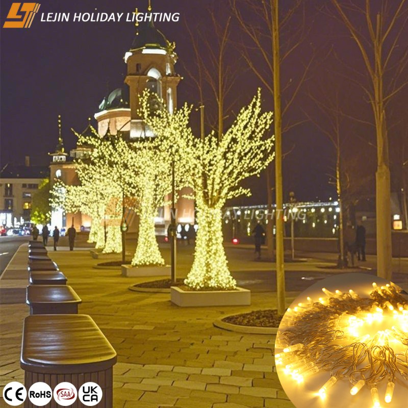
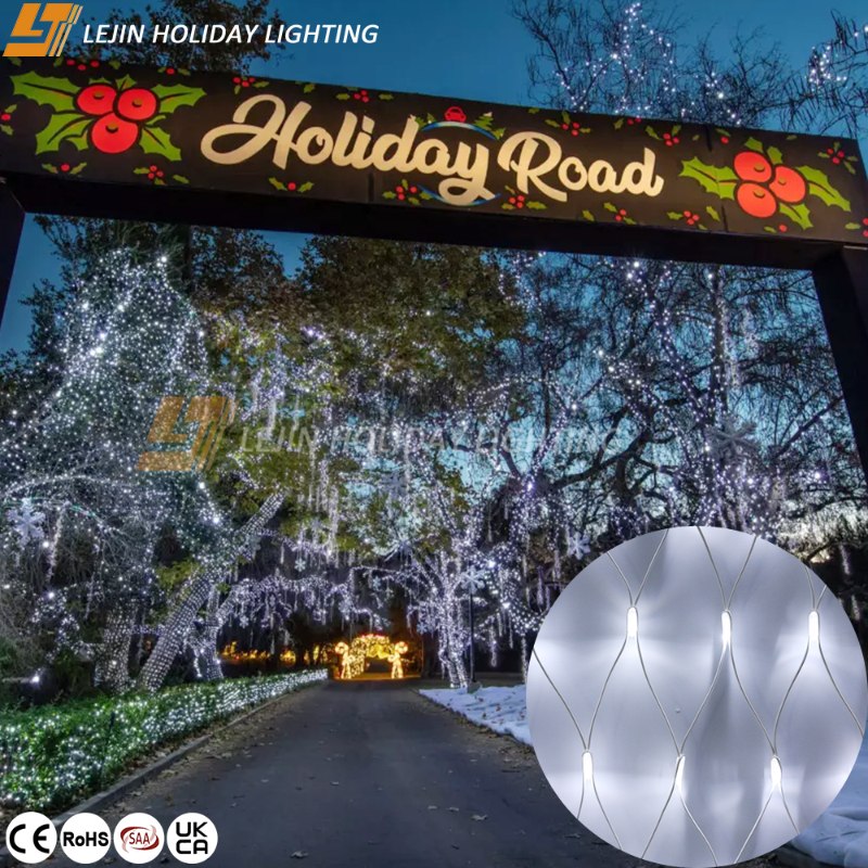
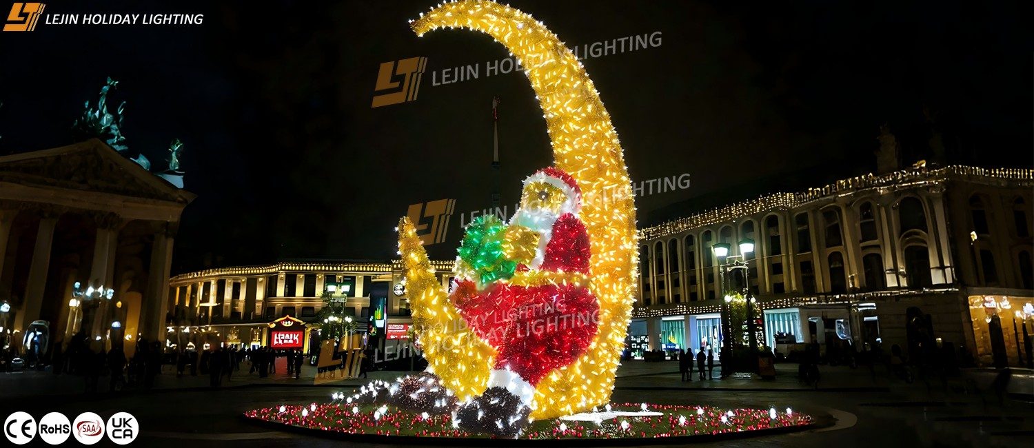
In outdoor Christmas lighting projects, the dynamic effect of light and shadow directly affects the appeal of the scene atmosphere. Smart 2D LED motif lights, with their slim and lightweight design, flexible adjustment functions, and strong adaptability to outdoor environments, have become a core choice for creating immersive light and shadow scenes. Through systematic control methods, they can transform traditional static decorations into interactive, linkable dynamic light and shadow installations, providing efficient and creative lighting solutions for large outdoor spaces such as parks and commercial districts.
Core Dynamic Control Technology of Smart 2D LED Motif Lights
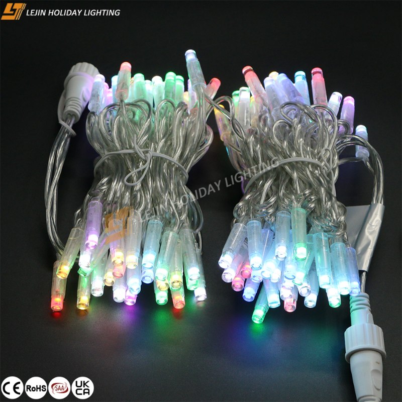
The dynamic light and shadow effects of smart 2D LED motif lights come from the cooperation of hardware and software. In terms of hardware, dense small LED beads are adopted, and the distance between beads can be adjusted according to the complexity of the motif, ensuring smooth and natural light transition. The core control components operate at high speed, avoiding flicker during dynamic changes.
The software system supports two control methods: it has built-in multiple preset dynamic modes such as gradient, chase, and flicker, and also allows custom effect design via a dedicated APP. Users can precisely set the on-off time and color of each motif light, and one control system can simultaneously manage multiple 2D LED motif lights, meeting the control needs of large-scale outdoor projects.
Dynamic Light Control Logic Design for Outdoor Scenes
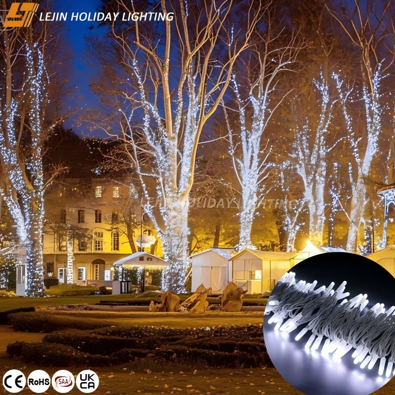
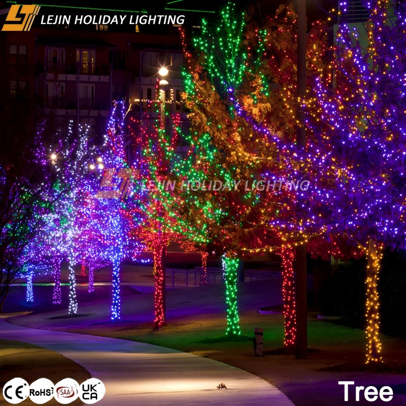
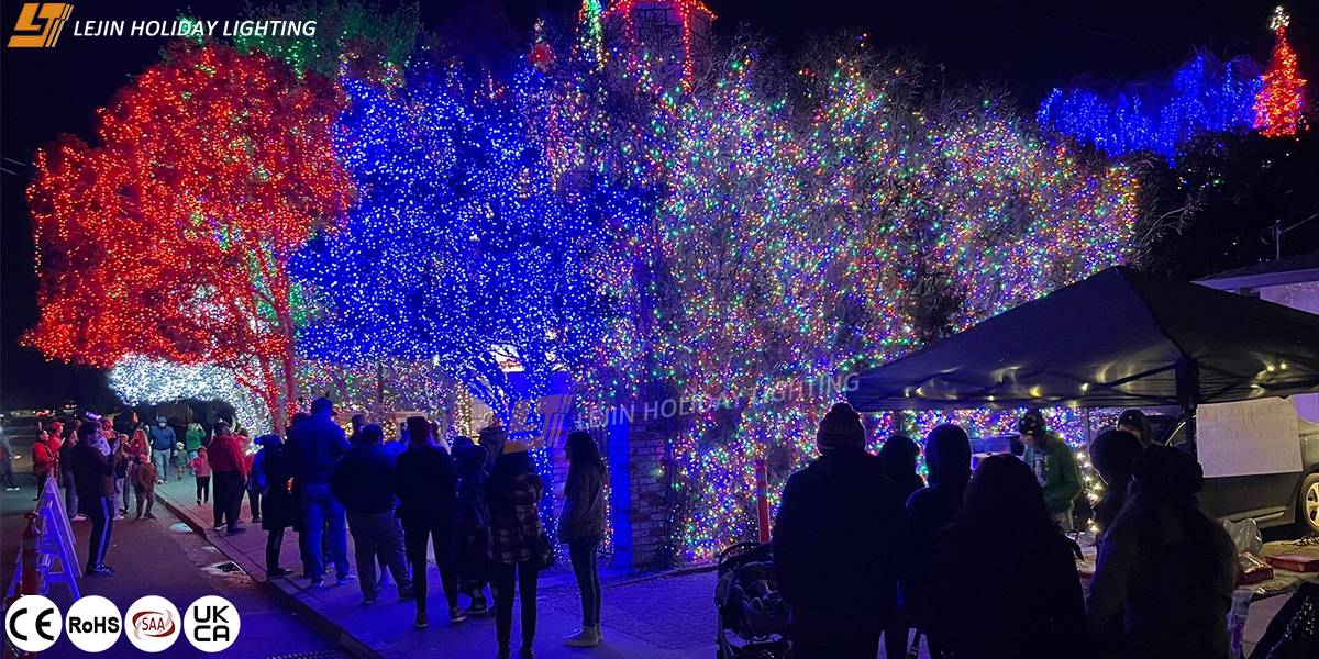
Considering the openness and complexity of outdoor projects, smart 2D LED motif lights adopt a two-layer control method of "zone control + global synchronization". In park lighting projects, they can be divided into different control zones according to landscape nodes, such as entrance area, trail area, and central square. Each zone is set with exclusive dynamic effects based on its function—for example, the entrance area uses a high-frequency flickering "welcome mode", while the trail area uses slow color gradients to guide foot traffic.
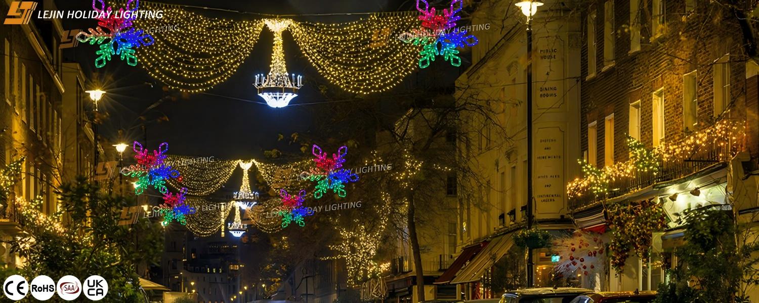
Global synchronization is achieved through precise time control, ensuring that dynamic effects in different zones coordinate seamlessly in timing. For instance, in cross-block Christmas decoration projects, when the main controller activates the "snow falling" theme, all 2D motif lights (including bell, star, snowflake motifs, etc.) will enter a blue-white gradient state simultaneously, cooperating with preset brightness rhythms to form a coherent light and shadow effect over a large area.
Guarantee of Dynamic Performance Stability in Extreme Environments
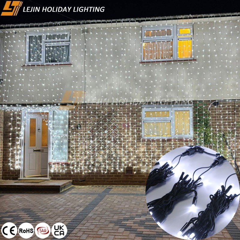
Outdoor projects may encounter complex weather conditions such as low temperatures, rain and snow, and strong winds. Smart christmas motif lights ensure stable dynamic control through triple protection design. They can work normally within a wide temperature range, without brightness or color being affected by temperature changes.
The circuit system has an automatic adjustment function: when some LED beads are damaged, the controller will automatically adjust the power of the remaining beads to maintain the integrity of dynamic effects. In addition, the wireless control section has strong anti-interference ability, ensuring stable communication in outdoor environments with complex signals from multiple devices, thus guaranteeing synchronization during large-scale linkage.
Energy Efficiency Optimization Strategies for Dynamic Light Solutions
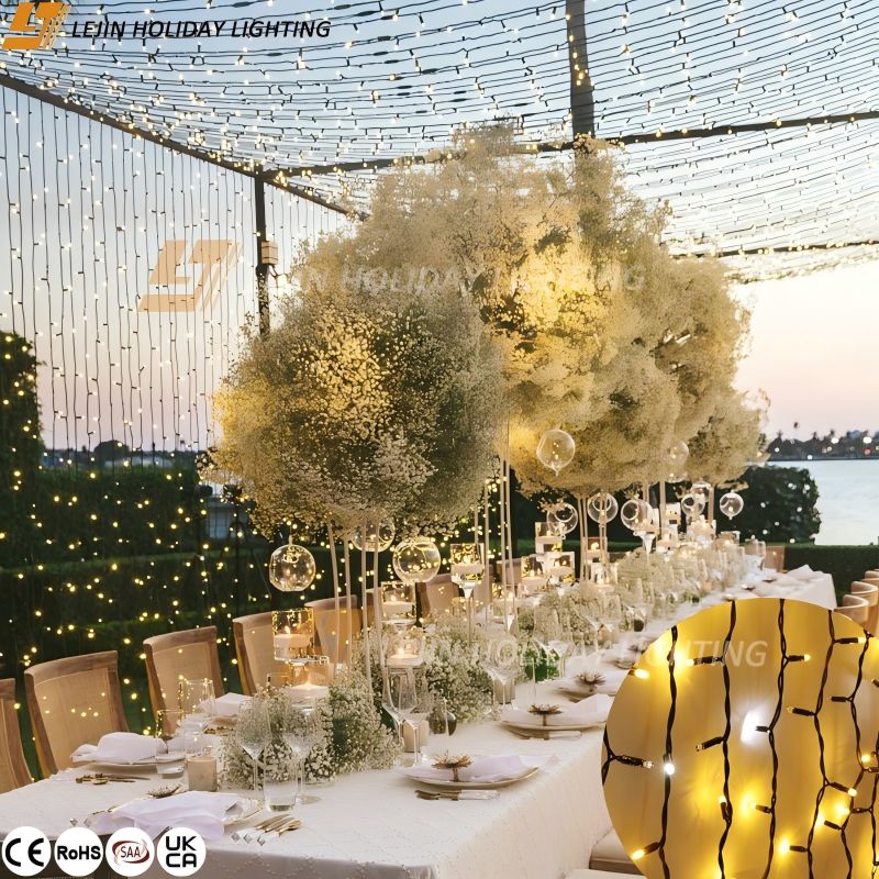
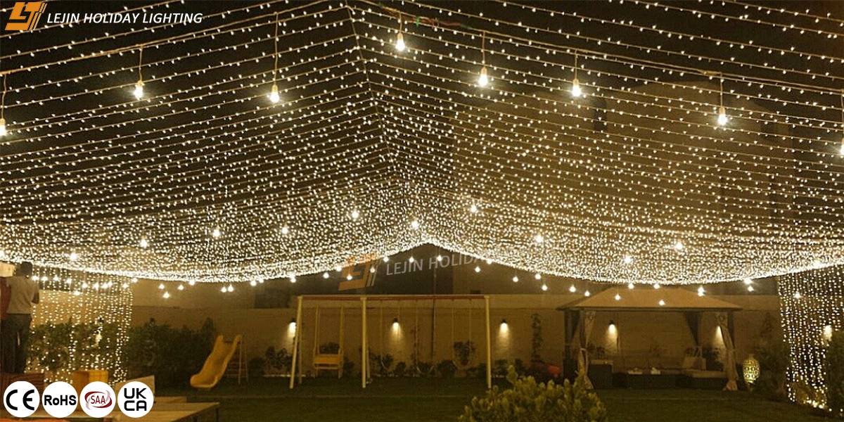
Large outdoor projects have requirements for energy consumption control. Smart 2D LED motif lights achieve a balance between energy saving and effect through dynamic dimming. The system is equipped with built-in light-sensing devices, which can automatically adjust brightness according to ambient light—maintaining low brightness standby during the day and gradually increasing brightness after dusk, which is more energy-efficient than the traditional always-on mode.
In dynamic modes, a "pulse power supply" method is adopted: power is increased during color changes to ensure clear transitions, and brightness is appropriately reduced during static periods. Taking a square lighting project composed of 1,000 2D LED motif lights as an example, this strategy reduces energy consumption while not affecting the visual experience of dynamic effects.
Practical Case: Dynamic Light Renovation Project in Commercial Districts
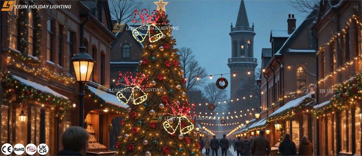
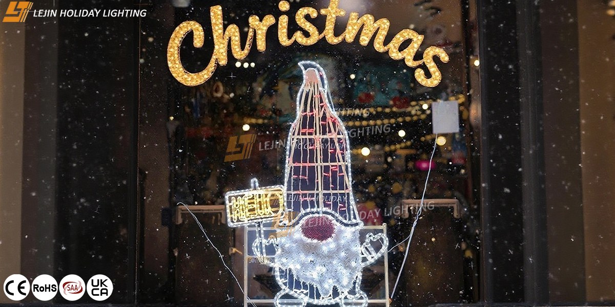
In a Christmas lighting project of a commercial district in a first-tier city, 200 sets of smart led christmas lights outdoor (including Christmas stocking, bell, and letter motifs) were used to create a dynamic light and shadow system.
The engineering team achieved efficient control through the following steps: In the early modeling stage, drawing software was used to draw the district's floor plan, marking the installation position and control zone of each motif light; in effect programming, multiple dynamic schemes such as "Christmas Overture" and "Midnight Carnival" were designed according to the district's architectural style, with switch times preset via the APP; in linkage debugging, the main controller was used to test cross-zone synchronization effects and optimize signal delay issues. The final effect showed that 2D motif lights outside street shops changed colors with music rhythms, and large motif light groups at corners simulated "breathing" through light and dark alternation, forming a layered dynamic light and shadow belt along the 300-meter-long district, with significantly more foot traffic during project acceptance than in previous years.
Upgrade Direction of Control for Smart 2D Motif Lights
As outdoor lighting projects demand more interactivity, the control technology of smart 2D christmas motif light is developing towards "scene perception". The next-generation system will incorporate intelligent recognition functions, which can capture pedestrian flow through cameras and automatically adjust the rhythm of dynamic effects—accelerating color change frequency to enhance attractiveness when there are many people, and switching to low-energy soft modes late at night.
Meanwhile, adding more advanced communication modules will further improve control distance and response speed, supporting larger-scale light and shadow linkage projects. For users of outdoor projects, choosing upgradeable led christmas lights outdoor allows them to continuously obtain new control modes and optimization methods through remote updates, extending the service life of the equipment.