How 2D LED Motif Lights Enhance the Night Atmosphere of Urban Plazas
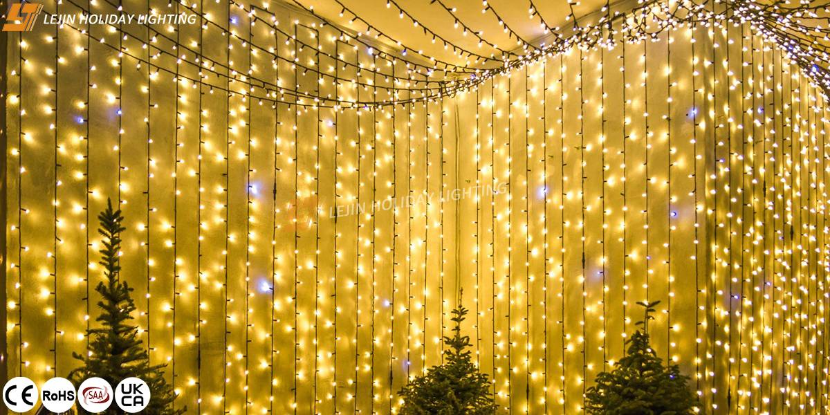
Driven by both the night economy and urban renewal, urban plazas are no longer just spaces for daytime activities. They have become core carriers for showcasing urban culture and activating nighttime vitality. 2D LED motif lights, with their flexible design forms, stable outdoor adaptability, and diverse functional attributes, are emerging as a key solution for overseas engineering clients looking to upgrade the nighttime atmosphere of plazas. They not only meet functional lighting needs but also infuse plazas with unique cultural and commercial value through the language of light and shadow.
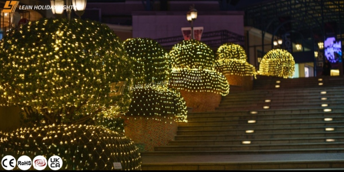
Outdoor Durability: Adapting to Complex Environments for Long-Term Stable Operation
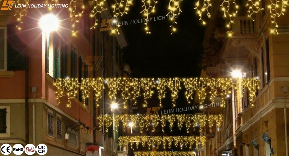
For outdoor urban plaza projects, equipment adaptability to the environment is a top consideration for engineering clients—and outdoor waterproof 2D motif lights have inherent advantages in this regard. Their core strengths lie in the dual protection of materials and protection standards: they mostly use high-strength metal materials that can resist sand, dust, and rain erosion. Meanwhile, they hold an IP65 or higher protection rating, enabling them to withstand extreme temperature differences from -40℃ to 50℃ and preventing cracking in low temperatures or aging in high temperatures. This reduces long-term maintenance costs, aligning with the needs of overseas engineering clients for long-term project durability.
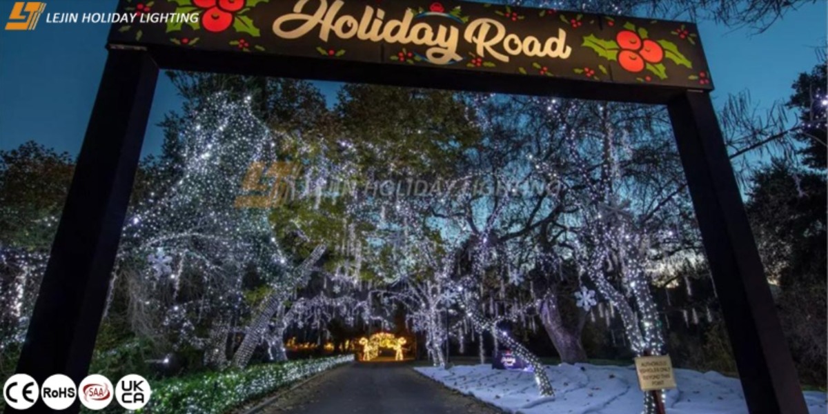
Design Flexibility: Customized Shapes to Convey Urban Cultural Symbols
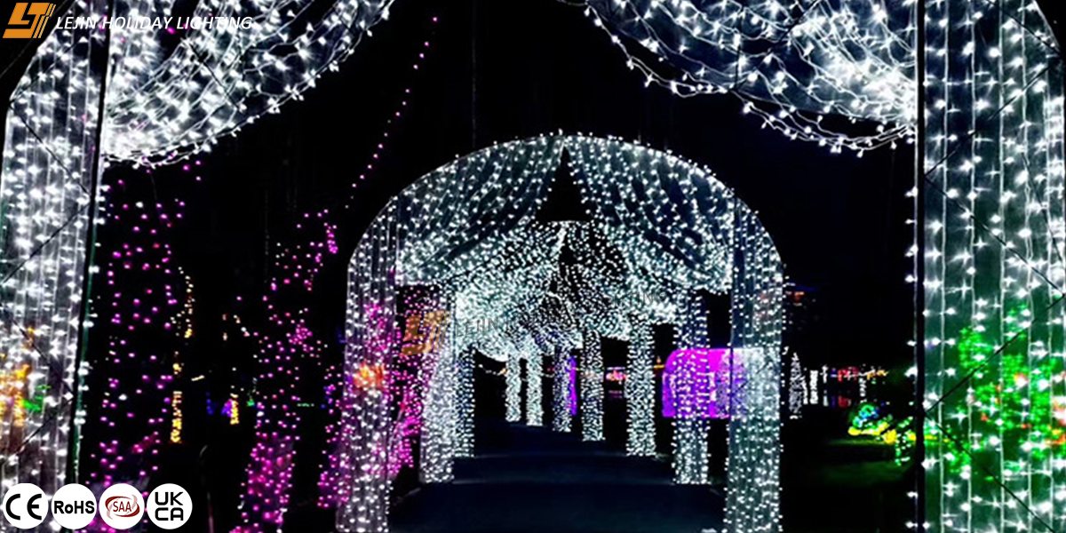
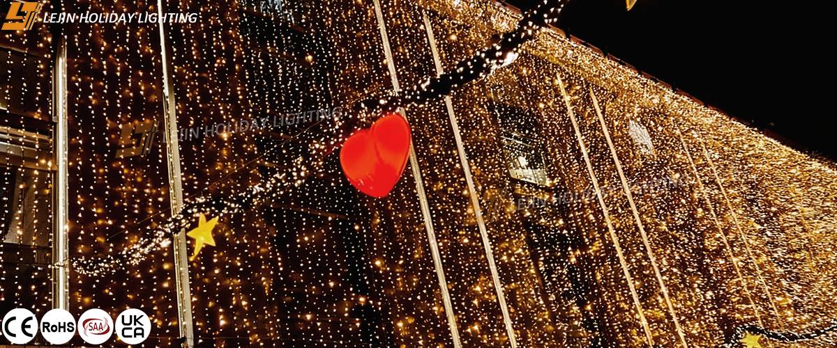
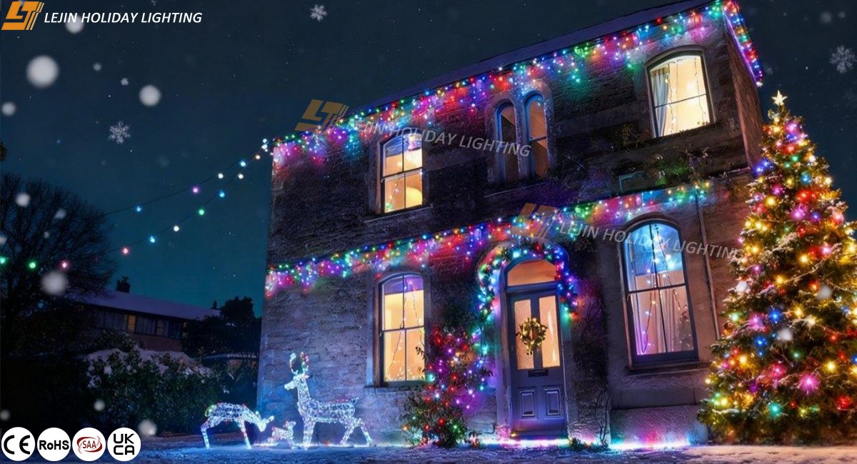
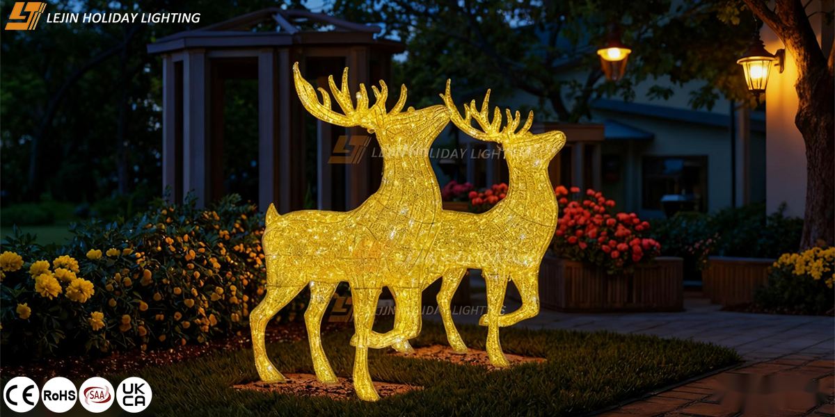
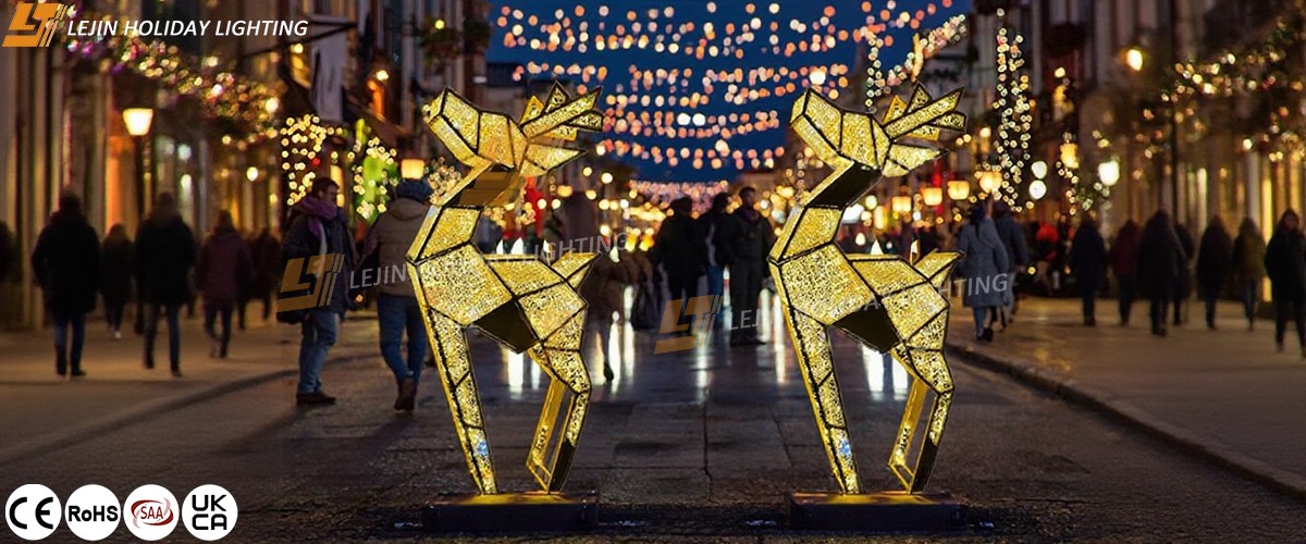
The nighttime atmosphere of an urban plaza needs to align with local culture and regional characteristics, and customizable 2D LED motif lights can precisely meet this demand. Engineering clients can customize shapes with different themes based on the plaza’s positioning and cultural background. For example, in plazas of historic European cities, shapes can be designed to mimic Gothic architectural outlines or classical sculpture lines, and warm-toned lighting can be used to recreate a sense of historical depth. In tropical Southeast Asian cities, shapes featuring natural elements like marine life can be customized, paired with cool-toned lighting to create a refreshing atmosphere.
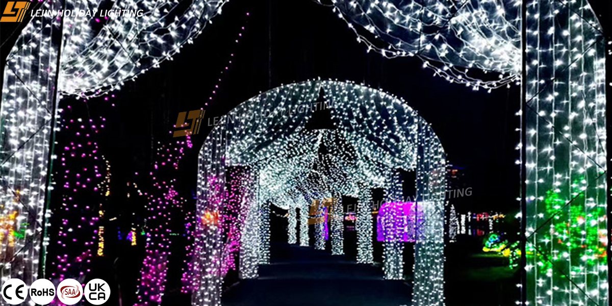
Functional Integration: Balancing Lighting and Interaction to Enhance User Experience
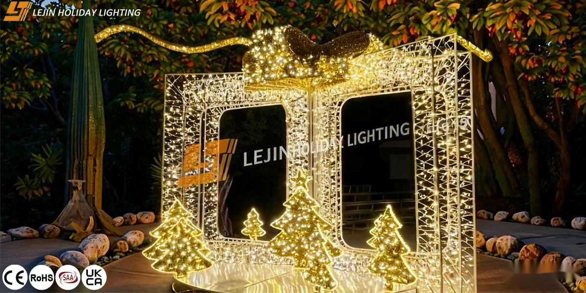
A high-quality nighttime plaza atmosphere requires not only “good looks” but also “practicality.” Smart 2D motif lights achieve dual upgrades in lighting and user experience through functional integration. Firstly, their basic lighting function meets the needs of pedestrian movement in plazas. Optical design controls the angle of light to avoid glare affecting pedestrians’ vision, while brightness can be adjusted according to time periods, balancing safety and energy efficiency. Secondly, some smart interactive 2D motif lights are equipped with intelligent sensor modules to support pedestrian interaction—when pedestrians approach, the lights switch colors or display dynamic flowing effects. This is particularly suitable for plazas popular with families and young people, enhancing the space’s fun and sense of participation. This “lighting + interaction” model transforms plazas from simple “pass-through spaces” into “stay spaces,” further activating nighttime vitality.

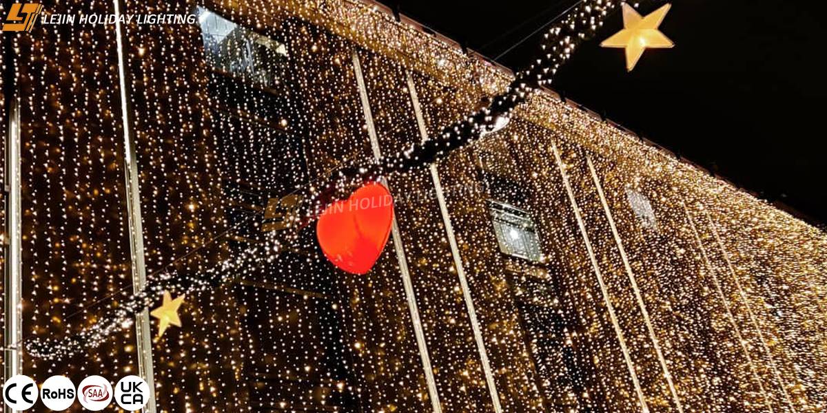
Sustainability: Energy Saving and Environmental Protection, Aligning with Green City Concepts
Current urban development generally prioritizes sustainability, and the advantages of energy-efficient outdoor 2D motif lights in energy saving and environmental protection fully meet engineering clients’ needs for green projects. In terms of light sources, they all use high-brightness LED chips, which save more than 60% energy compared to traditional sodium lamps and have a service life of up to 50,000 hours—reducing resource waste caused by frequent lamp replacements. In terms of control, they support intelligent control systems, allowing remote adjustment of the motif lights’ on/off status, brightness, and light effects. This eliminates the hassle of manual operation and enables “on-demand lighting,” further reducing energy consumption.
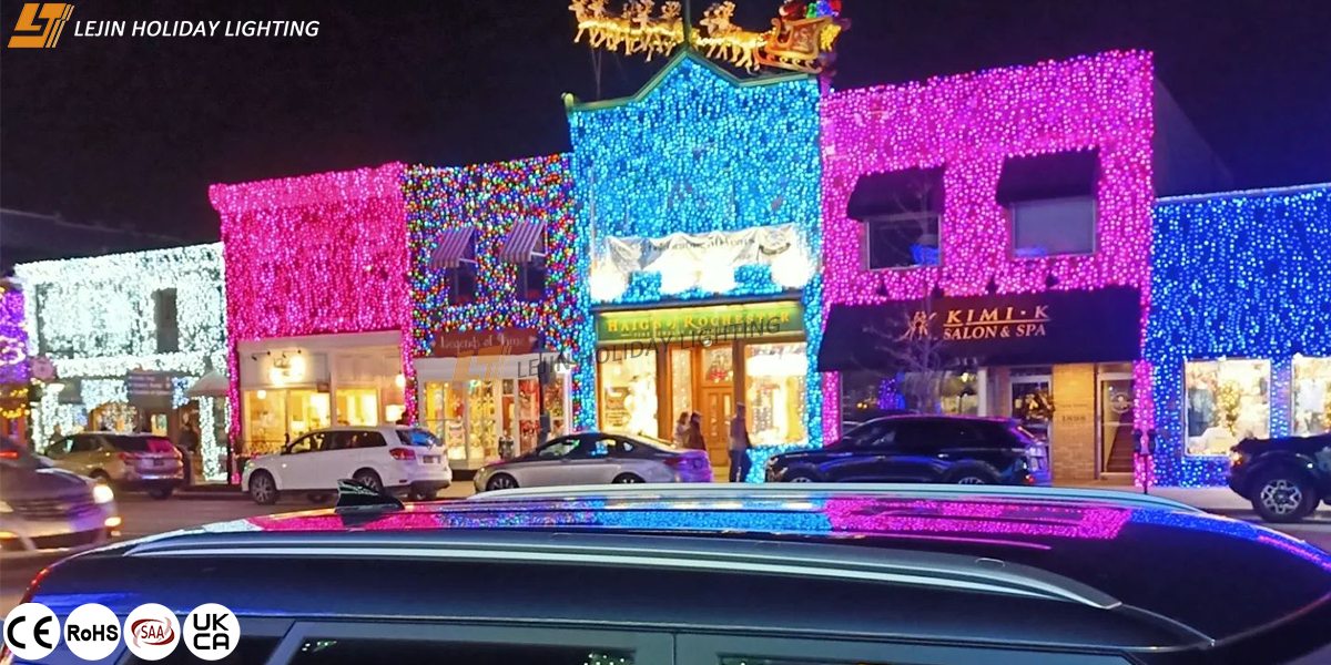
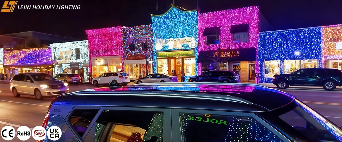
Case Reference: Practice at Markthal Plaza in Rotterdam, the Netherlands
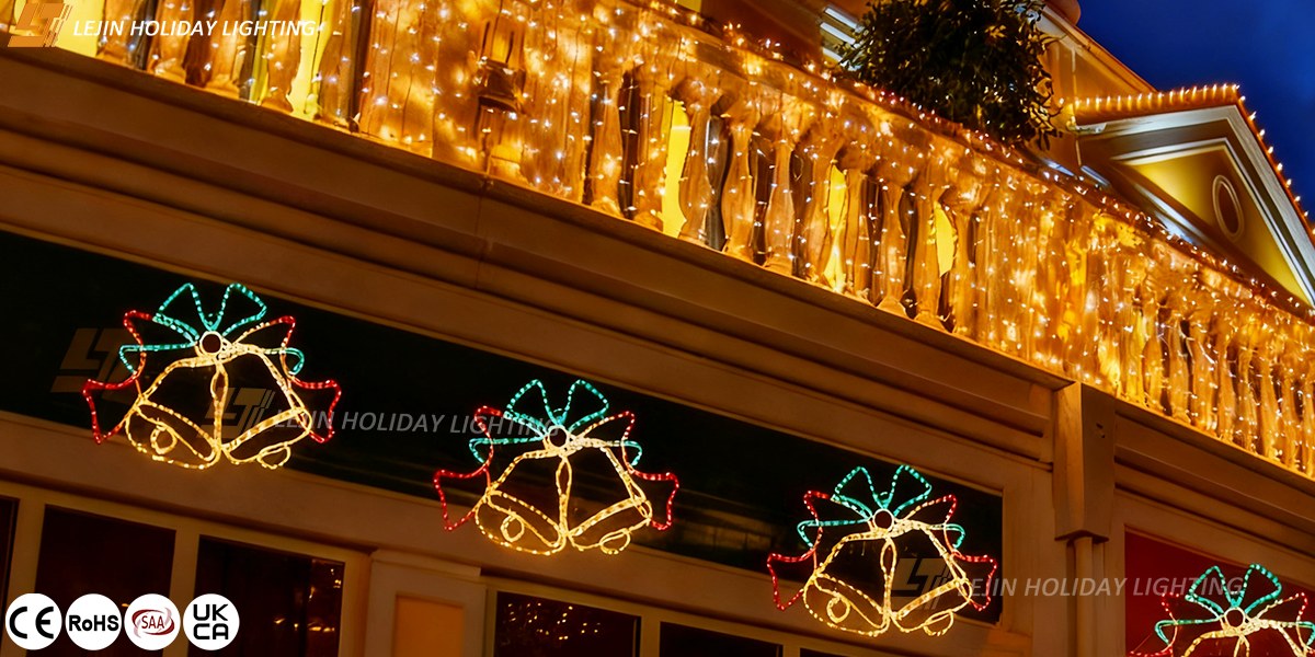
The nighttime upgrade project of Markthal Plaza (Market Plaza) in Rotterdam, the Netherlands, is a typical application case of outdoor 2D LED motif lights for plazas. The plaza is surrounded by residential buildings and commercial stores, and the engineering client’s requirement was to “attract tourists to stay without disturbing residents’ rest.” The final solution used christmas 2D motif lights themed around “market fruits and vegetables,” with customized simple linear shapes of tomatoes, onions, and bread installed beside the plaza’s railings and green plants. For lighting, warm white light was chosen, with brightness controlled below 200lux to avoid disturbing residents with strong light. Meanwhile, through intelligent system settings, slow color gradient effects were displayed from 6 PM to 9 PM, and the lights switched to a constant-on mode after 9 PM. After the project was completed, the plaza’s nighttime foot traffic increased by 40%, and the evening turnover of surrounding stores rose by 25%. This not only met residents’ needs for comfort but also injected vitality into local businesses, making the plaza a new highlight of Rotterdam’s night economy.